|
|
Maps And Artillery Boards
Transcribed 2019 by Howard Anderson from a pamphlet issued
by the British General Staff, December, 1916.
Available here as a PDF.
I. Maps.
1. General.
At the commencement of the war the extensive use of large
scale maps was not contemplated. Nothing larger than the 1:100,000
and 1:80,000 scale was issued to the troops, though a few
copies of maps on larger scales (of Belgium) were available
for the use of the General Staff. In the event of future mobile
operations it is intended to revert to the 1:100,000 scale.
When the present stationary phase began, artillery firing
was carried out mainly from the map, necessitating a larger
scale in order to get more accurate measurements and directions
between gun and target. For this purpose a 1:20,000 scale
was selected. The development of trench warfare, and the possibility
of mapping trenches in minute detail from air photographs,
made an even larger scale desirable ; hence for trench maps
a 1:10,000 scale has been adopted, the series being confined
to sheets on which the front lines of trenches fall, and those
in their immediate vicinity.
2. Pre-War Maps Of France And Belgium.
Speaking generally, the material which existed at the outbreak
of war consisted of-
A. In Belgium.
Small scale.-The 1:100,000.
Large scale.-The 1:40,000, 1:20,000, and 1:10,000. These
maps are produced by the Institut Cartographique Militaire,
and form the basis of all our present maps of the area.
The 1:10,000 existed in manuscript only, and was directly
reduced for publication on 1:20,000 scale, so that these two
maps are identical. It gives a very large amount of detail
and shows contours at 1 meter or 5 meters interval.
The 1:40,000 is also a reduction from the same survey. It
is not quite identical in outline, but the differences are
not great, and are usually attributable to dates of revision.
There are some slight differences In the conventional signs
used, and the contours are at 5-meter intervals.
B. In France.
Original surveys.
(a) Cadastral plans of communes. These were made between
1830 and 1850. They were never printed, but were drawn mostly
on the scale of 1:2,500, and three copies of each exist. They
are of varying degrees of value. In the Department of the
Somme they are exceptionally good, but elsewhere the error
of a line measured haphazard may amount to 30 yards. Each
commune has a 1:10,000 diagram, which shows the area and position
of each 1:2,500 plan. These are much less accurate than the
plans themselves, and the error of a casual line may amount
to 60-70 yards.
(b) 1:80,000 carte de l'etat major. This is the universal
topographical map of France, and is based on the cadastral
plans. Churches, crossroads, and important features are well
placed in position, but detail between is much generalized
and often out of date. Many sheets of this map were, however,
revised in the war area in 1913-14. Ground forms are shown
by hachuring. Enlargements to 1:20,000 from this map are of
little value.
(c) 1:50,000 nouvelle carte de France. This is a beautiful
topographical map, printed in colours, with contours and hill
shading. Only a few sheets are finished, and none in the area
of operations of the British armies.
(d) 1:20,000 plans directeurs of fortress areas. (These maps
must not be confused with the plans directeurs produced by
each French army in the field ; the latter are generally compiled
from cadastrals, whilst the former were made on the ground).
The area covered is along the frontier. Dunkirk, Lille, Valenciennes,
etc., are all surveyed in this series, which is incorporated
in the latest drawn British sheets. These are good maps, but
often out of date. They are contoured at 5-meter intervals.
(e) Mine areas (e. g., Noeux Les Mines). Several mine area
plans are in existence, but none of them are lithographed,
though blue photographic prints are available. Generally speaking,
they are good, but each case must be judged on its own merits.
Other French maps.
( f) 1:40,000 published by the Department du Nord. This is
based on an enlargement of the 1:80,000. It is a clear map
and gives valuable information as to levels and certain other
matters, but in general outline it is not better than the
1:80,000.
(g) 1:50,000. A direct enlargement of the 1:80,000, published
by the Service Geographique. This map reproduces faithfully
the errors of the original, and its chief value is that it
is clearer and easier to read. There is a similar enlargement
to 1:20,000.
(h) 1:100,000 Carte Vicinale, published by the Ministry of
the Interior. This is a clear map containing much valuable
information. Roads and railways are well shown and kept up
to date. The ground forms are poorly indicated, which detracts
from its value as a military map.
(i) 1:200,000, based on a reduction of the 1:80,000; published
by the Service Geographique. A good clear small scale map,
with contours.
(k) Various road maps published by private firms, such as
the Taride, Michelin, Campbell, and others. The first named
is an excellent map on which the roads are well classified.
Railway and canal plans.
A set of original survey plans at 1:1,000, called the "
Parcelaires," is in existence. In addition there are
plans at 1:10,000, which show curves, cuttings, and embankments,
and generally levels. These are made on a framework taken
from the 1:10,000 communal indexes to the cadastral series.
They are often inaccurate in outline (in terms of 50 yards),
and the detail away from the immediate vicinity of the railway
or canal is generally very faulty.
3. British War Maps.
The maps issued to the British expeditionary force may be
classed broadly under two heads-small scale (1. e., smaller
than 1:40,000) and large scale.
(a) Small Scale Maps.
1:380,180, or 8 miles to 1 inch, Belgium and Northeast Prance.-A
map showing on one sheet the whole of Belgium and the northern
part of France down to Beauvais and Compiegne. Main roads,
rivers, canals, and woods are shown; altitude is denoted by
coloured layers at 100-mile intervals (except below 100 miles.
where they are closer). This is a good small-scale strategical
map. It is not issued generally, but ma; be had on application.
1:200,000, or 4 miles to 1 inch,-This map covers, in about
20 sheets, Belgium and northern France down to Poitiers, Moulins,
etc. The series is not uniform in style throughout.
Sheets 1, 2, 4, and 5 were prepared before the war, and were
published on its outbreak. In these sheets the usual form
of British maps has been followed, 1. e., roads have black
outline and brown colour, and villages are drawn to shape.
Relief is shown by contours at 50 meters vertical interval.
On the first edition of these sheets many minor roads were
omitted, owing, to lack of time, but these have been added
in later editions. A combined sheet of parts 1 and 4 is published.
The remaining sheets were prepared and published after theo
outbreak of war, and are copies of the French 1:200,000 maps..
Roads are shown in red and villages by a symbol. Relief is
shown by form lines at 40 miles V.I. These sheets were produced
under great pressure and very rapidly. They are less elaborate
than the earlier sheets and contain less information. They
are also drawn on a different meridian.
The 1:250,000 is a useful strategical or motoring map.
1:100,000, or 1½ miles to 1 inch.-This map covers,
in 21 sheets, Belgium and the northern part of France. This
is a most important map, as it is the official tactical map,
and is the one that will be used in the event of mobile operations.
The sheets covering the Belgium area were produced before
the war, from the Belgian maps. The sheets in the French area
have been produced during the war, mainly by redrawing the
French 1:80,000 map, but utilizing information from the French
1:100,000, Taride and other maps. They are clearer and easier
to read than the 1:80,000. Relief is shown by form lines at
10 miles V.I. The 1:100,000 is a good map, but, like all maps
which can not conveniently be verified on the ground, it contains
errors, and it must never be relied on absolutely for the
existence of roads, shape of woods, or detail that may have
changed since the map was made. Maps on the 1:100,000 scale
are also available for Holland and Germany.
(b) Large Scale Maps.
Considering only the present theatre of operations, the large
scale maps fall into two distinct classes-Belgian area and
French area.
(i) Belgian area.-The maps issued are reproductions of the
Belgian maps published by the Institut Cartographique Milltaire.
No radical changes have been made, though steps have been
taken to improve and revise them in certain details.
The original maps (which were printed direct from the Belgian
plates) being somewhat difficult to read, the outline of certain
sheets has been redrawn, both on the 1:10,000 and 1:20,000
scale. This redrawing consists in copying the original outline,
drawing it finer in certain cases, and omitting unnecessary
detail, such as meadows, etc. A 5-meter interval for contours
has been adopted in place of 1-meter with the object of making
the map more legible. Minor corrections to detail have been
made in places where photographs on the German side, or revision
on our own side, give the necessary information. But on the
whole, the redrawn Belgian map can only be said to repeat
the information on the original in clearer form. These large
scale maps of Belgium, either redrawn or in their original
form, are available for the whole of Belgium.
(ii) French area.-The series of large scale sheets covering
Belgium has been extended to cover an area of France. As no
large scale maps of France exist except for certain fortress
areas, this extension was at first produced by direct photographic
enlargement of the French general staff 1:80,000 map. but
the area has now been covered by better maps produced as follows.
The area to the west of the front line is covered mainly
by new survey. This, in the northern area, was a rapid plane-table
survey (shown green) carried out early in 1915 under the superintendence
of Maj. Winterbotham, R.E. Later part of this was revised,
and a more deliberate survey was carried out along the southern
part of the line (shown red).
Immediately to the east of the front line an area (shown
yellow) has been mapped by compilation of old cadastral plans
corrected by air photographs. To the east of this again the
large scale maps are enlargements of the 1:80,000 (brown area)
until the fortress plans directeurs (blue area, along the
Belgian frontier) are reached. The plans directeurs, wherever
they exist, have been embodied in our maps; and in the area
west of the line (shown dark blue) have been revised on the
ground.
Generally speaking, the maps on the three scales, 1:10,000,
1:20,000 and 1:40,000, are identical, having in most cases
been drawn on the 1:20,000 scale, and enlarged or reduced
for the other two scales. In the area of the front line the
1:10,000 sheets have mostly been redrawn from cadastrals with
information from photographs embodied, as described above;
and the 1:20,000 has also been redrawn, or in some cases produced
by reduction from the 1:10,000. The latest 1:10,000 and 1:20,000
are therefore identical, but slight differences will be found
between them and the 1:40,000, as up to the present it has
been impossible to take up the redrawing of this map.
4. Trench Detail.
The trench detail is plotted from the air photographs either
by measurements from points of detail, or by reflecting the
image of the photograph onto the map by means of a camera
lucida. The latter method is applicable in close country where
there are plenty of fences, roads, etc., but fails in the
more open country to the south.
By either system, with the very much improved photographs
of the present day, trenches can be shown with a considerable
degree of accuracy with respect to the surrounding detail.
They should be seldom more than 20 yards out of their true
position.
Errors in " registration " sometimes throw trench
detail out of position, e. g., a trench may appear superimposed
on a hedge, whereas in reality it runs clear of it. This class
of error arises in printing and can not be altogether avoided.
5. Contours and Levels.
(a) Pre-war maps.-The original topographical survey of France
(the 1:80,000) was not contoured but hachured. The form lines
on our edition of this map are based on the levels and drawn
to fit the hachures. The contours of the French 1:200,000
map are also consulted. Those on our 1:100,000 of the French
area have the same basis. They show relief in general terms
only and are not of a high level of accuracy. The same remark
applies to the spot heights on roads and features. These were
fixed trigonometrically before any modern system of levelling
had been done, and many of them are considerably in error.
On the other hand, the 1:20,000 fortress plans directeurs
and the Belgian maps are well contoured-and the spot heights
refer to a modern system of levels.
(b) War maps.-The new large scale maps (1:40,000 to 1:10,000)
made during the war are well contoured in our own area. For
the area in German occupation, however, nothing is available
except the bench marks of the new levelling systems and the
old French contours. The contours on the compiled maps have
been drawn to conform in shape to the old contours, but are
controlled as to position by the bench marks, and checked
and corrected wherever possible by railway or canal plans
and air photos. They may be taken as generally good, but under
features are not shown. Occasional evidence has been got from
captured German maps, but generally of an unsatisfactory nature.
The contouring is the weakest feature of the present compiled
maps of areas in German occupation.
For more detailed information on this subject see "
Note on Levels and Contours " in course of publication
by general staff, general headquarters.
6. Degree of Reliability of the Maps in Various Areas.
(a) The maps of Belgium are generally fairly accurate, but
they do not attain to the minute precision of the ordnance
survey of the United Kingdom. Ample opportunity has occurred
recently of testing these maps, and though it is found that
in many areas the original work stands well as regards local
detail, there are occasional errors of some importance. Main
roads have, for example, been found to be out of position
and to be incorrectly drawn. There is some evidence that the
trigonometrical points were not plotted very carefully on
the original drawings, and the effect of this is to throw
out the whole detail in their vicinity. A haphazard range
measured from this map might be found to be 30 to 40 yards
in error.
(b) In the French area the degree of reliability varies with
the material used in compilation. (See diagram 6.)
The rapid plane table survey (shown green on diagram) was
pushed through as quickly as possible, and suffered in accuracy
accordingly. In the main, however, it is good accurate work,
and is faulty only in the towns, which were left unrevised.
The errors as a rule do not exceed 40 yards.
In the deliberate revision and survey (red area), which were
carried out later, the errors do not usually exceed 20 yards.
The contouring was carefully done, and is reliable.
In the compilation area (yellow), mapped from old cadastrals
corrected as far as possible by air photographs, the errors
may be taken over the greater part of the area as not exceeding
20 yards, but where detail has changed on the ground, and
no photos are available to correct it, large errors are possible.
In the plan directeur area (blue) the maximum error may be
taken to be 30 yards, except where detail has changed, when
it may be very large.
In the plan directeur area within our lines, which has been
revised on the ground (dark blue) the accuracy may be taken
as the same as that of the red area.
In the enlarged 1:80,000 area (brown) the error may be 50
yards at important points of detail, and up to 200 yards in
other parts.
7. Sheet Lines.
The large scale maps are plotted by rectangular coordinates
from the Belgian origin which is on the meridian of Brussels,
those of the French area having been made to conform to the
Belgian system. Each sheet (1:40,000) measures 32,000 meters
by 20,000 meters, and at the corner of each sheet are printed
the distances of the sheet lines from the origin. (See diagram
5.)
The basis is the 1:40,000 sheet, which is identified by a
number, e. g., " Sheet 28." Each 1:20,000 sheet
covers one quarter of the area of a 1:40,000 sheet, and is
identified by the letters NW, NE, SW, SE., denoting its position
on the 1:40,000 sheet. A 1:20,000 sheet is thus called 28
NW
Each 1:10,000 sheet again covers one-quarter of the area
of a 1:20,000 sheet, and is identified by the number 1, 2,
3, or 4. The northeastern 1:10,000 sheet of a 1:20,000 area
is thus called 36 SW 2. In addition the 1:10,000 sheets are
given names, as this provides an easy means of reference when,
as often happens, a combined 1:10,000 sheet is made.
The preparation of combined 1:10,000 sheets, made up of parts
of two or more adjacent regular sheets, has been necessary
in many cases in order to provide a sheet on which the trench
line falls conveniently. These combined sheets are in general
of the same size as the regular sheets.
8. System of Squares.
Over the sheet has been superimposed a grid showing squares
of 1,000 yards. This is merely for convenience in indicating
localities, and obviously can not fit exactly with the sheet
lines, which are in terms of meters. The grid has therefore
been placed with its central point in the centre of the 1:40,000
sheet, and allowed to overlap the sheet lines along the edges
of the map. (See diagram 5.) On the east and west edges the
grid line 17,500 yards from the centre very nearly coincides
with the sheet line, the overlap being the difference between
17,500 yards and 16,000 meters (half the length of the sheet).
This is only 6.5 feet, and is covered by the thickness of
a single line on the map, so that for all practical purposes
it is negligible.
At the north and south edges, however, we get an overlap
which is the difference between 10,000 meters (half the width
of the sheet) and 11,000 yards (the nearest grid line). This
overlap amounts to 192.4 feet, and appears on all large scale
maps. The diagram shows how it appears on the 1:20,000 and
1:10,000 enlargements of the different portions of the original
1:40,000 sheet, e. g.:
(a) In 1:20,000 " N. W." the full overlap of 192.4
feet appears along the northern edge, but the southern edge
being the centre of a 1:40,000 sheet the grid and sheet lines
coincide.
(b) 1:10,000 sheets " S. E. 1." On the northern
edge the grid and sheet lines coincide, while the southern
edge shows half the overlap, 1. e., 96.2 feet.
(c) 1:10,000 " S. E. 3." The northern edge shows
half the overlap, while the southern edge shows the full overlap.
9. Use of the Squares.
The large rectangles on the map, lettered A. B, C, etc.,
are divided into squares of 1,000 yards side, which are numbered
1, 2, 3, etc. Each of these squares is subdivided into four
minor squares of 500 yards side. These minor squares are considered
as lettered a, b, c, d.
A point may thus be described as lying within square B.6,
M.5.b, etc.
To locate a point within a minor square, consider the sides
divided into tenths, and define the point by taking so many
Diagram 1.
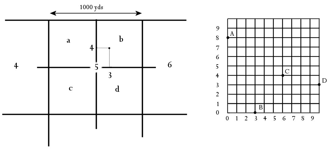
tenths from W. to E., along southern side, and so many tenths
from S. to N. along the western side, the southwest corner
always being taken as origin, and the distance along the southern
side always being given by the first figure.
A point may thus be described as located at M.5.b.3.4, i.e.,
three divisions east and four divisions north from the southwest
corner of square M.5.b. (See diagram 1.)
By a simple extension of this method the point may be more
accurately located if sides of the minor squares be considered
as divided into 100 parts, and the point described by using
four figures.
These distances, represented by either one or two figures,
east and north of the origin, are called square coordinates,
as distinguished from trigonometrical coordinates, which are
the distances east or west and north or south from the origin
of the sheets.
In the diagram above, the square coordinates of point C are
8.4 (on the two-figure system), or more accurately 62.42,
i.e.
62 hundredths east, and 42 hundredths north from the south-west
corner of the square.
The coordinates of A are 0.8; of B, 3.0; of D, 0.3 in the
adjoining square.
Note that in using these coordinates the numbers 0 to 9 should
be used, but not 10, or mistakes may occur.
10. Cards for use of Square Coordinates.
The system of square coordinates can also be used with the
1:100,000 map, or, indeed, on any map which is divided into
Diagram 2.
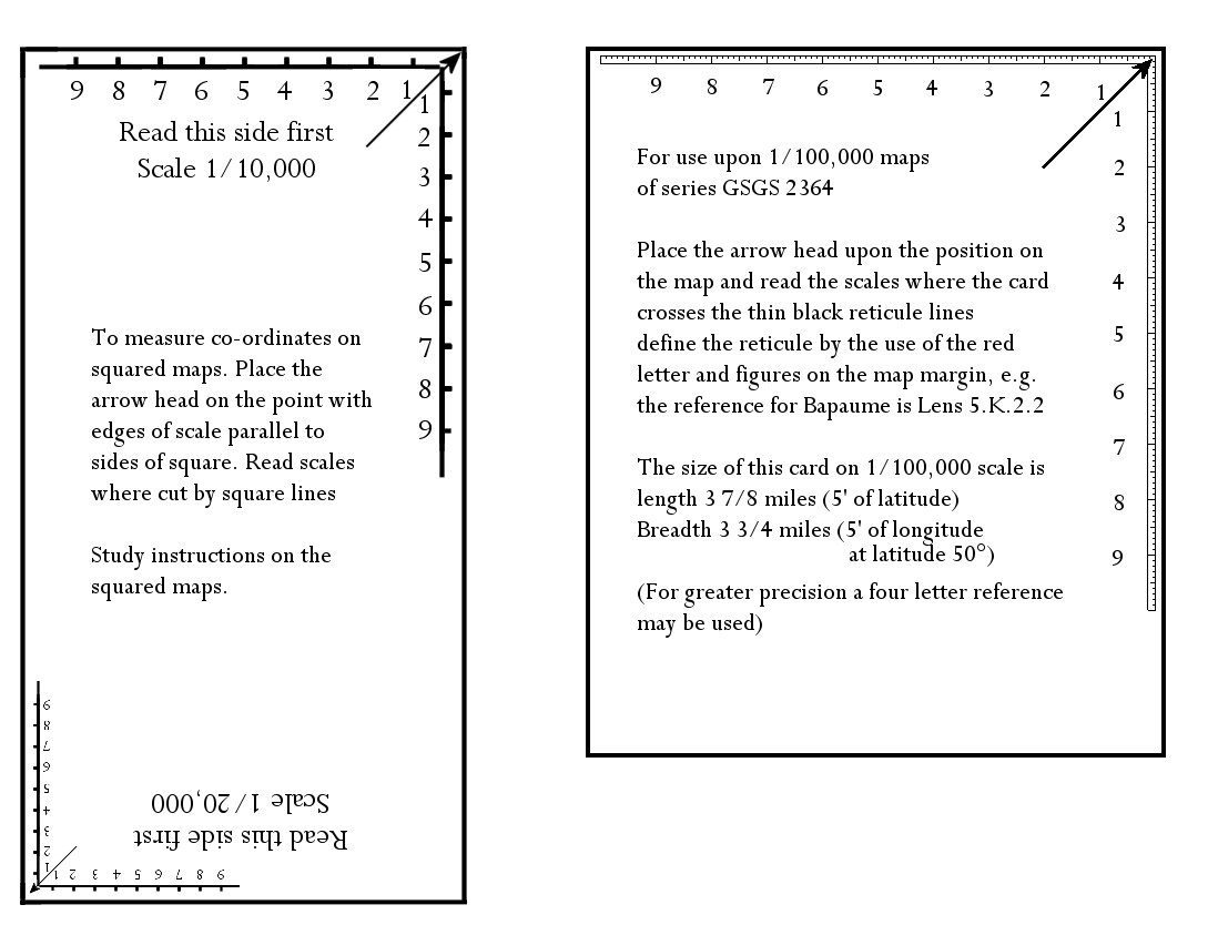
squares or rectangles or sectors, which can be defined by
reference numbers or letters. To facilitate the use of coordinates
on the maps, special cards have been prepared and issued.
Diagram 2 shows the cards for the 1:20,000 and 1:10,000, and
for the 1:100,000 scales. The two large scales are at opposite
ends of the same card.
11. The North Point.
In any system of rectangular sheets, as soon as a point is
reached far from the origin on which the system is based the
vertical sheet lines no longer point true north and south.
The inclination to the sheet lines of the meridians of longitude
(I. e., true north) increases with the distance from the origin.
Hence the vertical sheet lines of our large scale maps, which
are all rectangular, are not true north and south. On sheet
28, for instance, the angle between sheet line and true north
is 1° 04'.
It is necessary to consider this inclination only when plotting
a bearing taken with a magnetic compass. All bearings and
directions fixed instrumentally by survey companies are given
with reference to the grid or sheet lines. This may be conveniently
referred to as " Grid north."
Diagram 3.
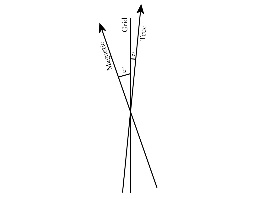
a= 1° 04'.
b=12° 30'.
a+b (i. e., the variation of the compass) =13° 34'.
Diagram 3 shows grid north, with true and magnetic north for
sheet 28. (See also diagram 5.)
The magnetic *variation in the year 1916 for the sheet quoted
is 13° 34' west of true north, or 12° 30' west of
grid north.
It should be remembered that any compass may have an individual
error in variation of as much as half a degree east or west,
and users should be careful to ascertain the actual variation
of their compasses. This can be found by taking a bearing
with the compass on some point whose true bearing has been
ascertained either by measurement on the map, or, better still,
by instrumental observation.
II. Artillery Boards.
1. Requirements of the Artillery.
The data required by the Artillery are:
(1) The position of the gun.
(2) The bearing of the aiming point.
(3) The range of the target and its bearing from the aiming
point.
The position of the gun may be fixed:
(a) By instrumental or plane-table resection from trigonometrical
points.
(b) By similar resection from points not trigonometrically
fixed.
(c) By reference to local detail.
By (a) the position can be obtained within the accuracy required
for artillery. By (b) the position may be obtained with sufficient
accuracy by an experienced observer, but there is a liability
to error. A position fixed by (c) is always liable to error,
as detail in a topographical map can never be relied on for
absolutely accuracy of position. It will readily be seen that
if a gun position is marked on a map by method (b) or (c),
the line to the aiming point, especially if that point is
near the gun, may have an angular error which, if projected
over a long range, will lead to a large displacement on a
distant target.
Assuming that the position of the gun and the hearing to the
aiming point have been satisfactorily determined, and that
the position of the target on the map is known by its square
co-ordinates, the gunner has the data that he requires to
his hand ; but if he plots these positions on the ordinary
unmounted map, errors and inconveniences result, which can
only be eliminated by the use of an artillery board.
The sources of error are as follows:
(1) It is very difficult to make accurate measurements of
range or bearing on an unmounted map, and still more so if
the gun, aiming point, and target are on different sheets.
(2) However true to scale a map may be when first printed,
distortion is bound to arise owing to the expansion and contraction
of the paper according to the state of the atmosphere ; and
if the map be mounted without special precaution it will certainly
be much and unevenly stretched, causing errors both in scale
and angle.
The errors arising from these sources are far from negligible.
They increase with the range, but at any range they should
be eliminated as far as possible; and they are minimized by
the use of artillery boards.
2. Artillery Boards.
An artillery board consists essentially of a flat rigid surface
on which the required positions are accurately plotted, and
permitting of the accurate measurement of angles and distances.
This surface is obtained by mounting drawing paper, backed
with linen, on a base which is Title affected by damp or change
of temperature. The base usually takes the form of a zinc
sheet, which is in turn mounted on a wooden board or frame.
The framework of a map is the network of trigonometrical points,
which for artillery purposes is absolutely accurate. The distances
of these points, north, south, east, or west of the origin,
and the position of the sheet lines and of the grid with reference
to these points, are known. The portion of this framework
necessary to cover the particular area required by the gun
or battery is plotted on the artillery board. It is a duplicate
of the framework of the map, but not liable to distortion.
On this rigid framework the grid and the positions of the
gun (or directing gun in the case of a battery) and aiming
point are plotted and drawn by the field survey company. An
arc divided to read degrees and 10', and if possible of greater
radius than the range required, is laid down on the board,
with its zero through any selected point and its centre at
the directing gun ; or a separate arc may be used for each
gun by using different radii. These arcs enable the bearing
or switch angle to be read with accuracy, and obviate the
errors which are involved by using a small protractor.
No detail is really essential on an artillery board, for
it can always be obtained from the map, the framework being
the same ; but it is usual to have the German trenches accurately
shown by drawing or pasting them on. Any other detail required
can be drawn. Boards so prepared are handed by the field survey
company to the battery. It rests with the battery to plot
the positions of targets as received.
Owing to the amount of drawing involved in the preparation
of boards by the above method, which is theoretically the
most accurate, a large number are now prepared by drawing
squares of the grid on the board, and cutting the map into
sections and pasting them in their proper positions in this
framework. Any errors due to expansion or contraction of the
paper are thus confined within small areas. This method is
not only quicker but has the advantage that all the detail
is on the board, which many gunners prefer. The errors due
to this method of preparation are less than the known errors
of the maps themselves.
On the Belgian maps the trigonometrical points are occasionally
incorrectly plotted. When this is the case, and the board
is prepared by pasting the map on in sections, the true positions
of the incorrectly drawn trigonometrical points are plotted
on the map. When measuring ranges and bearings from the gun
position to points in the vicinity of such trigonometrical
points, a correction must be made proportionate to the difference
between the true and the false position of the trigonometrical
o point.
For field artillery, boards are sometimes prepared by simply
pasting the map itself on a board. This method, however, eliminates
no errors, for paper when wetted for mounting always expands
more in one direction than in another, thus giving rise to
considerable angular errors. This method provides a rigid
surface on which measurements can be made, but it should only
be used for short ranges, and when time does not permit of
more accurate methods.
The majority of artillery boards are prepared on the 1:20.000
scale. Those for heavy and siege artillery are always made
with the paper mounted on a zinc plate. For field artillery
the 1:10,000 scale is often employed, and in place of the
zinc plate millboard is sometimes used ; or, when seasoned
wood is obtainable, the paper is mounted on the board itself.
When zinc is not used the basis of the map is less rigid,
and it is advisable that before daily work, a known length
(so many lines of thousand yard squares) should be measured
along and across the board, in order that the range correction
for the day may be ascertained. This correction would be a
certain percentage to be added to or deducted from the ranges
measured on the board.
For very long range guns, boards have been prepared on the
1:40,000 scale.
The field survey companies identify points either by square
positions or by trigonometrical coordinates. Trigonometrical
coordinates are' independent of sheet lines and facilitate
the calculation of the range and bearing.
The usual method is, however, to measure ranges and bearings
on the board, and for this purpose one system of identifying
points is as good as the other. All artillery boards should,
however, have axes marked from which trigonometrical coordinates
can be plotted if necessary. Except by the field survey companies,
positions are never communicated by trigonometrical coordinates.
3. Calculation Of Range And Bearing.
Where the trigonometrical coordinates of both gun and target
are known, the distance and bearing (from grid north) between
them can be accurately computed. Errors in plotting are eliminated,
and it is a matter of indifference whether gun, target, and
aiming point are on the same or different sheets of the maps,
for the trigonometrical coordinates run continuously through
all sheets.
It will be assumed, for the sake of example, that the position
of the gun G and the direction to the aiming point A have
been determined by the topographical section, and that a new
target T has afterwards been fixed and its coordinates furnished
to the battery.
It is required to find the distance GT and the bearing of
T from G (i. e., the angle which GT makes with grid north).
Diagram 4
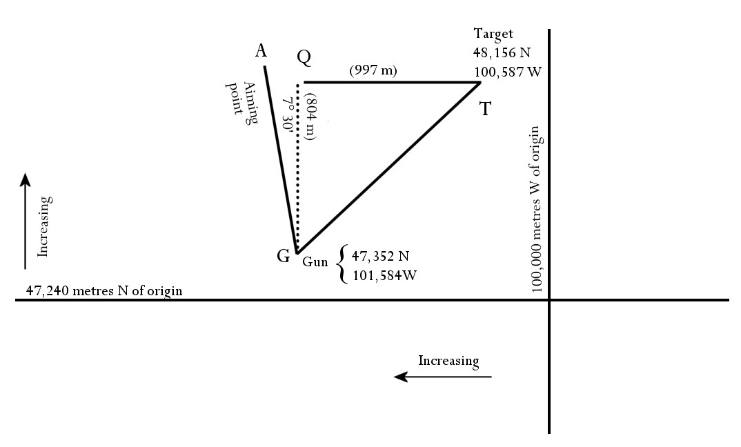
In the triangle GTQ
TQ is the difference between 101,584 and 100,587 meters=997
meters.
GQ is the difference between 48,156 and 47,352 meters=804
meters.
997
The angle TGQ is the angle whose tangent is 997/804 which
works out at 51° 7'.
Add this to the already determined angle AGQ (7° 30'),
which gives the switch angle AGT.
The range TG is found by the simple trigonometrical formula
TGQ=QC/cos QGT i.e., by dividing the distance QG
(804 miles) by the cosine of QGT (51° 7'). This gives
a result of 1,280 miles, which can be converted into yards.
?
Diagram 5.
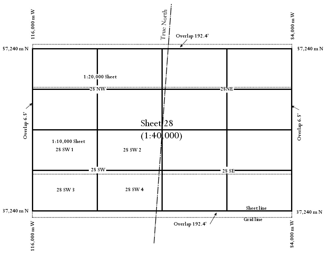
Showing subdivision of a 1:40,000 sheet, and incidence of
the grid lines, etc.
NOTE.-Amount of overlap and inclination of meridian have
been exaggerated for clearness.
The overlap E. and W. is only 6.5 feet, and the grid line
and sheet line are therefore practically coincident.
|
|